Ingress Protection Testing

At Quanta Labs, we perform many IP tests for a variety of different industries.  There are two standards for IP testing: IEC 60529 and ISO 20653. These standards aim to provide engineers with more detailed information than vague marketing terms such as waterproof or dustproof. This article provides an overview of exactly what IP ratings are and what level of protection for your product or application.

IP Testing Overview

IP (Ingress Protection) ratings are classified by categorical codes and measure of an enclosure/electronics ability to resist items entering it. The adoption of this classification system promotes uniformity in methods of describing the protection provided by the enclosure and in the tests to prove the various degrees of protection, they now provide engineers with a convenient, practical way to compare levels of sealing.

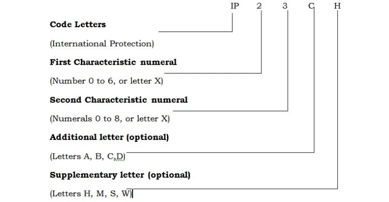
The IP code is composed of two numerals:

The first numeral refers to the protection against solid objects and is rated on a scale from 0 (no protection) to 6 (no ingress of dust).

The second numeral rates the enclosure’s protection against liquids and uses a scale from 0 (no protection) to 9 (high-pressure hot water from different angles). 

Where a characteristic numeral is not required to be specified, it shall be replaced by the letter “X” (“XX” if both numerals are omitted.) Additional letters and /or supplementary letters may be omitted without replacement. Where more than one supplementary letter is used, the alphabetic sequence shall apply.

Below are the tables which specify what each “digit” in the IP level relates to for the IEC standard.
IEC IP Testing

The tests establishing compliance with any one of the lower degrees of protection
need not necessarily be carried out provided that these tests would obviously be met if
applied i.e. passing an IP3x test would cover the requirements for IP1x test. Best thing is to check what your customer requires products level of protection or check the environment the product will be going into and performing tests.

Solids ingress protection IP5x and IP6x are concerned with dust protection. IP5x allows some dust to enter, but not enough to affect equipment operation. IP6x is fully dust-tight and requires a vacuum line through the enclosure. The vacuum tests are performed for a period of between two and eight hours, depending on how much air volume is drawn through the cabinet. The duration of the non-vacuum IP5x is eight hours.

Examples Products with IP rating

Most outdoor industrial products are rated IP67/IP67 which is the highest level of dust protection and IPx5 is protection against power washing. IPx7 is protection of product being submerged in water 1m below the surface. If products are likely to be cleaned using pressurized jets, they should be rated at IPX5 or above. IP ratings for handheld electronic devices tend to focus on keeping both users and contents safe from inadvertent contact with mechanical or wired parts, but it’s common to see IP ratings for full protection from water ingress (IP65+) depending on their intended application. RFID Lock Electric Door Lock is rated IP65.The Outdoor Industrial 4G Router and Yealink W59R Rugged Wireless Expansion Handset are rated IP67.

Here is an another example showing the IP rating for common household items to give a frame of reference.

The IEC standard is broader than the ISO standard which outlines the protection of electrical equipment in road vehicles while the IEC tests are more general purpose. 

ISO IP Testing

Here is an example of an IP test that can be quoted. IP16KB

The marking of an enclosure with the IP code IP16KB means:
(1) Protection of the electrical equipment within the enclosure against foreign objects with a
diameter of more than 50 mm (protection against foreign objects).
(6K) Protection of electrical equipment within the enclosure against harmful effects resulting
from water directed against the enclosure from any direction as a strong jet with increased
pressure (protection against water).
(B) Protection of persons against finger contact with hazardous parts within the enclosure \(protection against access).

The product would have to survive all three tests in order to be rated IP16KB. The standard doesn’t specific how many units need to pass in order for an enclosure to be rated. 1 unit is the minimum however testing more than one give the design and reliability engineering team more confidence.

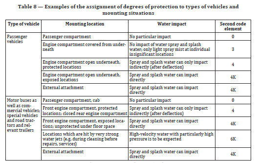
Unlike the IEC standard, the ISO standard offers the recommended IP test for the Type of vehicle and the mounting location of that vehicle.
Another notable difference between the ISO and IEC spec is the test IPx9k. IPx9 is testing from an IEC standard and is for electrical equipment while IPx9K is testing from an ISO standard and is for electrical equipment mounted on road vehicles. IPX9 testing requires that the force of a water jet is measured during the water test while IPX9K testing requires that the pressure of the water jet is measured during the water test.

  1. The distance for the test nozzle for the IPX9 test is 175 mm, plus or minus 25 mm and the ISO IPX9K test is 100 to 150 mm.
  2. The impact of the water is measured in terms of force for the IPX9 test while it is measured in terms of pressure for the IPX9K test.

Summary

At Quanta Labs, we perform many IP tests for a variety of different industries.  There are two standards for IP testing: IEC 60529 and ISO 20653. These standards aim to provide engineers with more detailed information than vague marketing terms such as waterproof or dustproof. This article provides an overview of exactly what IP ratings are, how you can use them, and what level of protection for your product or application.

Some notable differences are:

  • There are two standards for IP testing: IEC 60529 and ISO 20653. IP (Ingress Protection) rating are classified by categorical codes and measure of an enclosure/electronics ability to resist items entering it. The adoption of this classification system promotes uniformity in methods of describing the protection provided by the enclosure and in the tests to prove the various degrees of protection, they now provide engineers with a convenient, practical way to compare levels of sealing.
  • The tests establishing compliance with any one of the lower degrees of protection
    need not necessarily be carried out provided that these tests would obviously be met if
    applied.
  • The standard doesn’t specific how many units need to pass in order for an enclosure to be rated. 1 unit is the minimum however different configurations can be tested.
  • If products are likely to be cleaned using pressurized jets, they should be rated at IPX5 or above. IP ratings for handheld electronic devices tend to focus on keeping both users and contents safe from inadvertent contact with mechanical or wired parts, but it’s common to see IP ratings for full protection from water ingress (IP65+)
  • IP5x allows some dust to enter, but not enough to affect equipment operation. IP6x is fully dust-tight and requires, a vacuum line through the enclosure.

Getting Paid to Break Stuff

Getting Paid to Break Stuff

I get paid to break stuff.

Or, at least, that is what I tell my friends and family when they ask what I do for work.  I’m three years out of school working at an environmental test lab as a mechanical engineer Quanta Laboratories is where I run temperature, humidity, altitude, shock, vibration, drop, and many other types of tests for clients.  There are many standards and test plans that are designed to provide a laboratory simulation of the damage-producing motions, forces, conditions, and sequences of specific environments.  Clients from the customer products, medical device, government, and other industries approach us when they want to understand characteristics about their prototype or ensure their product will survive the intended environment. I would like the reader to take away engineering and work insights that have deepened by Christian faith from this article.

Continue reading “Getting Paid to Break Stuff”

ReGENERATION PROJECT 2019

regen project

ReGeneration Project 2019

One thing I am thankful for in this Thanksgiving season, the people at the Regeneration Project putting on this annual event.  The purpose of this event is gathering a community of people who want to examine the tough questions and realities of the Christian faith.  It is now more than ever important for Christians to know what and why they believe.  As someone who has grown up in Church, I am constantly learning more and refining my purpose from events, sermons, and people I talk to. Attending this event has helped me find more clarity and comfort about life, meaning, morality, and purpose in today’s pluralistic society.

Continue reading “ReGENERATION PROJECT 2019”

Understanding 3D Printing Titanium

What Is 3D Printing Titanium?

3D printing with metals is still a new process; however, as the machines and materials continue to drop in price it will become more adopted by different industries for similar use cases.  One of the most desired industrial quality metals is titanium due to its lightweight, high strength, resistance to corrosion, melting point properties.  It also a great material for osseointegration or formation of bone tissue on an implant surface.

Direct Metal Laser Melting

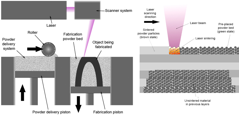
(DMLM) employs a high-powered laser to fuse layers of powdered metal into three-dimensional solid parts. The advantage is that the more complex the component becomes, the more economical the process becomes.  Below are graphics showing the process

Direct Metal Laser Melting

Here are some specs for DMLM according to i.materialise.com,

  • Wall Thickness: The minimum thickness of a ‘wall’ of your 3D model can be as low as 0.4mm! For most of our materials this value typically is in between 1 and 3mm: for ceramics it is even 3-6mm. To be on the safe side, we’d suggest you nevertheless to stick to a minimum wall thickness of at least 1mm for titanium prints (especially if you plan to make something small such as the band of a ring).
  • Detail Size: Thanks to our DMLS printers, you can go into a very fine level of detail. The distance between the wall of your model and the surface of a detail can be as little as 0.25mm!
  • Dimensional Accuracy: Due to heating and cooling processes in the titanium, a 3D print can be slightly bigger or smaller than your original design intended. However, DMLS is by far the metal 3D printing process with the highest dimensional accuracy. With titanium, dimensional accuracy is generally better than 2% for outer dimensions.
  • Geometry: Angular shapes, right angles and straight lines will tend to look less attractive than organic or freeform shapes. Angles of less than 35° tend to lead to poorer surface quality. Steep angles of more than 35° tend to lead to better, smoother and nicer surfaces. An overhanging structure (e.g. underside of a table) will tend to have poor surface quality. The most ideal shape to make when using DMLS is that of a mesh. These shapes make it easy to design for this process and deliver the best results

Another popular process used is EBF or Electron-beam fabrication.

Electron-Beam Fabrication

taken from here: https://goo.gl/uTLpkv

Electron-beam fabrication doesn’t require a bed of material since it melts a feed of titanium wire in successive layers to create the desired structure.  This process is similar to FDM of plastics printing in that the energy source of the laser heats up the material in a freeform manner.  The scalability of this process is also similar to the FDM process in that the size of the printed product is a function of vacuum build space and the diameter of the wire. A typical deposition rate is 2500 cm3/hr (150 in3/hr) and the three parameters that affect the build time are translation
speed, wire feed rate, and laser power.  There also is a trade-off between high deposition rates and the quality of the grain microstructures. The quality of microstructures affect the tensile properties and the resistance to fatigue, fracture, and crack propagation.

Taken from Wikipedia, this table shows current plastic and metal 3D printing processes:

Type

Technologies

Materials

Extrusion Fused deposition modeling (FDM) Thermoplastics (e.g. PLAABS), eutectic metals, edible materials
Granular Direct metal laser sintering (DMLS) Almost any metal alloy
Electron beam melting (EBM) Titanium alloys
Selective heat sintering (SHS)
Thermoplastic powder
Selective laser sintering (SLS) Thermoplasticsmetal powdersceramic powders
Powder bed and inkjet head 3d printing, Plaster-based 3D printing (PP) Plaster
Laminated Laminated object manufacturing (LOM) Papermetal foilplastic film
Light polymerised Stereolithography (SLA) photopolymer
Digital Light Processing (DLP) liquid resin
 

Design Guidelines for Metal Printing

With 3D printing, there can be a fair amount of trial and error; however, there are some common design obstacles documented and understood. It’s important for engineers to know about this obstacles even before designing the CAD models.  There is also variation in different 3D metal printers; the laser spot size and translation speed are essential to knowing.

The design obstacles that should be understood are part orientation, porosity, density, and deformation.

Part orientation

3D printing creates parts with anisotropic properties, which means they have different mechanical properties in different build directions. Some of the available free gcode software can let you change the print shape of each layer such as honeycomb, linear, star, triangle, and more.  The parts have higher tensile strength in the X and Y direction than they do in the Z direction. Hence, part orientation needs to be considered before printing, and the designer must pay attention to where certain areas will sustain stress.

Quick side note on holes and overhangs

The general rule of thumb is to not design a gap or hole under 0.5 mm as well as overhangs should not extent more than 0.5mm (with no support structure) and its good practice to use chambers (or at least fillets) on overhanging features.  Support can be used to create elaborate overhangs and holes, but the designer must be mindful of the moments and stresses on those features after the support is removed.

Porosity

While 3D printed structures are optimized for their weight, the designer must be mindful of porosity leading to cracks and accelerated fatigue.  This occurs when very small cavities form within the body of a part as it is being printed. The 3D printing process itself or the powder used can cause the small cavities.  The particles may not fuse correctly when there is not enough powder or when the laser intensity is too low; however, spatter ejection can occur when too much power is used.

The best way to avoid these problems to buy certified material and tune the machine parameters of power, spot size, and spot shape for a given material and print job.

Density

The porosity is inversely related to density; for load-bearing applications, a density of above 99 percent is required resist fatigue or cracking under pressure. There is a tradeoff between density and build time; the bigger particles reduce the build time, and the density of the part, as well as, the smaller particles increase the build time and density.  Volume flow rate also affects the density of the part.  A constant volume flow rate will allow for an evenly distributed part; a variable flow rate will increase the porosity of the part.

Cracks in structure expand exponential, that why porosity and density are so important with powder-based processes.  It is hard to predict the creep or deformation in a non even distributed part.

Deformation

If the part in purposed for functional use, the effects of expansion and contraction must be anticipated.  Expansion and contraction can be due to high stress or temperatures that cause the residual stress to exceed the tensile strength of the part during and after the build.

During the build, the highest magnitude of stress is found at the edge of the material and the build plate.  The hot material is going to curl away from the build plate which creates a tensile stress at the edge and a compressive stress in the middle.  Even if the part remains adhered to the build part, the stress can deform the part due to the unloading of the stress.  A substrate is added to the top layer of the build plate to reduce this effect, but the high-level way to reduce this temperature-educed stress is to reduce the temperature range of the material.  Besides modifying the laser length and distribution, the material can be heated before its hit with the laser to reduce the temperature difference of operating process.  The support structure and proper part orientation can help reduce the deformation by strengthening the part during the build; however, the excess support material can absorb the heat needed to fuse the particles together (increasing the porosity of the material).  Engineers can optimize the shape and build process of the support structure for each build by formulas or the method of trial by error and most of the metal printing research has been focused on reducing deformation of the printed material.

Now having talked about the problems with metal printing, it’s important to highlight the advantages of creating a metal printed part.

Advantages of creating a metal printed part

Metal printing’s benefits over traditional manufacturing techniques include,

  • The process doesn’t require special tooling parts, and one machine can make many different parts
  • Create part with features that cannot be cast or otherwise machined and can reduce the number of parts and fasteners in assemblies
  • Parts can be optimally designed for each use case to minimize material and maximizing yield strength
  • Compared to plastic printers, prototypes can now be functional hardware made out of the same material as production components.  Currently available alloys include 17-4 and 15-5 stainless steel, maraging steel, cobalt chromium, Inconel 625 and 718, aluminum AlSi10Mg, and titanium Ti6Al4V

With all of these advantages, why don’t more companies implement these systems?

The need for volume and speed is greater than the need for complexity and optimal design.  Molding and subtraction processes have already been streamlined to crack out hundreds of parts before a 3D printer can make one.  Traditional manufacturing also have a much greater build area compared to 3D printers

The 3D printing services are facing enormous inertia with traditional manufacturing; companies already have processes and training done for traditional machines.  There is a learning curve that will have to be overcome before 3D metal printing can reach its full potential.  Metal printing is much more complex and requiring more design training than plastic printing.

The Future of Metal Printing 

Metal printing’s current target is creating low volume complex parts that need to be strong and lightweight.  For other parts, other manufacturing processes are more cost-effective and faster.

There will be hybrid additive/subtractive machines (such as DMLS and CNC machining) as to print a rough draft of the product and refine it with the subtractive process as well as create complex geometries on subtractive parts. The key to metal printing’s adoption will depend on widespread design knowledge and cost of 3D printing.


3D Printing in Medicine: Fountain of Youth? BioPrinting Analysis

I attended a wonderful talk put on by GABA (German American Business Association) on 10/11/17 about how 3D bioprinting’s ability to print precise, complex and individual features has opened new roads for medicine.  The speakers shared the current efforts to create organs and tissue and what the future has in store.  The presentation including a diverse panel of six speakers, Dr. Jenny Chen, MD, Dr. Melanie Matheu, Dr. Mayasari Lim, Dr. Nabeel Cajee, DDS FICOI, Tom Anderton, who each explained the impact of bioprinting in industry, academia, education/global outreach, and patents.

Jenny Chen

Founder/CEO of 3DHEALS is trained as a neuroradiologist, and her company is focusing on curating healthcare 3D printing ecosystem. Her main interests include medical education, 3D printing in the healthcare sector, and artificial intelligence. She is also a current adjunct clinical faculty in the radiology department at Stanford Healthcare.  She was also the event’s moderator and lead each Q&A section with each speaker as well as an open panel Q&A at the end.

Dr. Mayasari Lim

Founder and CEO of SE3D, a startup focused on next-generation bioprinting tools for accelerating research and education in the biomedical and biotech fields. Previously, she was a professor in Bioengineering at Nanyang Technological University (NTU), a top engineering university in Singapore. Her research expertise included stem cell engineering, bioprocess design, bioprinting and tissue engineering.  She is greatly passionate about training next generation minds for the future of bioprinting. She currently teaches at the Fung Institute for Engineering  Leadership at UC Berkeley. Her background obtained her Ph.D. degree in Chemical Engineering at Imperial College London and her BSc in Chemical Engineering at UC Berkeley.  She believes the future outlook of 3D bioprinting will be used for creating personalized medicine, drug screening, tissue replacement and future organ transplant. She hopes to accelerate the future of bioprinting by offering educators an affordable bioprinters, coupled with comprehensive curriculum and laboratory teaching materials to trigger research and exploration.

She began the event with describing the three main ways of achieving bioprinting: laser-assisted bioprinting, inkjet bioprinting, and microextrusion bioprinting.  Below are videos showing the various processes.

Laser-assisted bioprinting

Inkjet bioprinting

Microextrusion bioprinting


She pointed out the obstacles and tradeoffs in the bioprinting process; mechanical properties versus the biological interaction of the cells printed as well as the post-processing of bioprinting.  The process of placing down the cells was the easy part, keeping the cells alive and maintaining their intended purpose in the structure was the difficult part.  There are chemical, physiological, biological, mechanical, and cell to cell interaction that must be monitored.  These factors can be influenced in a controlled environment by adjusting the temperature, pH, humidity, and other factors as well.  This monitoring is critical to understanding how bioprinted structures can be suitable for the real world environment.   She also explained the obstacle of iPS reprogramming factors to make sure the cells had specific tasks to perform when they were printed since it is hard to program the cells to do what they do.


Dr. Matheu

Co-founded Prellis Biologics in October 2016, with the mission to create fully vascularized human tissues and organs from transplantation. She orchestrated a cross-pollution solution of laser technology at the center of her Ph.D. thesis with biology to creating the tiny blood vessels, known as microvasculature, necessary for tissue engineering applications. Without microvasculature, organs are starved of oxygen and nutrients.  Dr. Matheu brings her multi-disciplinary experience in specialized laser microscopy, cell biology, physiology, and biophysics to build microvasculature and additional layers of tissue with near instantaneous speeds and single-cell precision.

Consumer grade bioprinters do not have the resolution to print microvasculatures required for tissues and organs.  They have a high resolution holographic 3D laser that very similar to 3D lithography.  Hopefully, in the near future, consumer-grade bioprinters will be able to reach the resolution and precision needed to create the tiny blood vessels and Prellis’s process becomes more streamlined so they can make a dent in the global organ shortage.

Here is a gif from their website: https://www.prellisbio.com/ showing the process


Dr. Nabeel Cajee

Dr. Cajee is a comprehensive dentist with an interest in advancing implant prosthodontics as a clinician, innovator, and educator. Dr. Cajee is a member of the faculty at the University of the Pacific School of Dentistry in San Francisco and the Dental Ambassador of 3DHeals. He is a recognized Fellow of the International Congress of Oral lmplantologists and the American Academy of Implant Prosthodontics.  He also spent time researching in the Pacific Angiogenesis Laboratory. Dr. Cajee hopes 3D/Bioprinting will unlock creative and deliverable therapies for better patient outcomes.
He highlighted the FDA’s clearance for implantable 3D printed titanium may allow his practices to eliminate inventory of stock implants and parts and create personal products to the patient’s need.  He emphasized dental technology is transitioning from closed systems of technology that is formulaic in process to open systems which may unlock creativity and lower costs; he believes 3D Printing and Bioprinting (in-time) will open up possibilities to advance dental treatments and expand access to care.  He also noted the use of platelet-rich fibrin (PRF) in many dental surgical procedures such as tooth extractions, dental implant surgery, and bone and gum augmentation. Dr. Cajee has documented cases of patient’s not needing to take medications after tooth extractions and implant surgeries due to the accelerating healing properties of PRF.
With PRF,  fibrin, growth factors, and white blood cells are taken from the patient blood.  Since they are from the patients own blood, they are not rejected from the body, rather speed up the healing. The process is the blood is drawn before the procedure normally while the patient is getting numb for the surgery. The blood is then put into a centrifuge at 2700 rpms for 13minutes. After 13 minutes, the blood is separated into three layers – 1) clear liquid or plasma layer 2) red layer rich in red blood cells  3) yellow thick layer which is the PRF layer.
You may visit his talk here: https://www.youtube.com/watch?v=WsyVGYVcl24
Visit his website here: https://www.drcajee.co/about-dr-cajee &  Instagram @drcajee

Tom Anderton

Tom is currently at Squire Patton Boggs, he was formerly General Counsel, Secretary at Zonare Medical Systems and Vice President, Intellectual Property & Legal Affairs at Presidio Pharmaceuticals where he oversaw the legal function at Presidio. Before Presidio, he was the Associate General Counsel and Chief Patent Counsel at Monogram Biosciences, Inc., where he built Monogram’s IP portfolio.  In the talk, he shared the history of patents related to 3D printing and bioprinting, the expiration of important patents in the additive manufacturing industry after 2009 have enabled the expansion of 3D printing into many different technology areas.

In Summary

While 3D printing is well underway for dental and prosthetics, significantly reducing time and costs of production, one of the most exciting developments is the possibility for bioprinting of tissue and organs.  It will be interesting to see how bioprinting further impacts industry, academia, education/global outreach, and patents.

4D printing

4D Priniting

Self-Assembly and Reaction

4D printing is printing 3D objects that can assembly into another object or preform a reaction to certain conditions. However, the objects need a catalyst to perform their transformation such as water, temperature, light, or other factors. One major player in this movement, who coined the term “4D printing” and created the Self-Assembly Lab, is Skylar Tibbits. He along with Stratsys’s R&D departments and the Connex 3D printer have made important progress in this field. This video clip of a self folding cube by the Self-Assembly Lab shows what can be done within the field of 4D printing. There are more videos from the lab located here.

He saw what nanotechnology was changing in medicine and he is applying the same idea to infrastructure and manufacturing. He isn’t looking to create smart materials that replace designers and engineers, but rather create “programmable materials that build themselves.” It will be interesting to see more to come from this field.

Related Posts

About the Author

Max Murphy is Mechanical Engineering student in his Junior year at California Baptist University. He is interested in the implications of 3D printing or positive manufacturing for mechanical design.  In the summer he is was an intern with Soundfit, one of the companies that is part of the Bay Area Advanced Manufacturing Hub (BAAM), where he is gained hands on experience with a 3D printer and scanner.  He was also an intern with Neodyne Biosciences working with the R&D and Q&A departments.

Biomimicry With 3D Printing of Shapes and Surfaces

Biomimicry

Biomimicry is a approach to design that mimics specific systems or processes found in nature. It has been around a lot longer than 3D printing.  The collage depicts several innovative designs that are directly based on certain properties found in nature.

6BiomimicryExamples

shark_06_1

Sharkskin

For example, Speedo’s Sharkskin swimsuit uses a counter-intuitive approach to reducing drag with a rougher surface that slightly increases turbulence. It’s modeled on the denticles on the surface of a shark’s skin that allow for faster movement than a completely smooth surface. The dimples on a golf ball have similar effect.

The slide show, 7 amazing examples of biomimicry, goes through them in better detail.

Also see the slide show titled “14 Smart Inventions Inspired by Nature: Biomimicry”.


Shinkasen Bullet Train

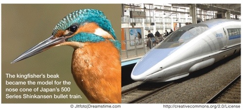
The Shinkansen Bullet Train is another great example of basing designs off things found in nature.  One of the problems with the Shinkansen train was the great loud noise that was created by the friction between the air and the train’s body.
Kingfisher beak and bullet train

“Eiji Nakatsu, an engineer with JR West and a birdwatcher, used his knowledge of the splashless water entry of kingfishers and silent flight of owls to decrease the sound generated by the trains.”
Excerpt from “Shinkansen Train” on Ask Nature

kingfisher_eharrington

Kingfishers move quickly from air, a low-resistance (low drag) medium, to water, a high-resistance (high drag) medium. The kingfisher’s beak provides an almost ideal shape for such an impact. The beak is streamlined, steadily increasing in diameter from its tip to its head. This reduces the impact as the kingfisher essentially wedges its way into the water, allowing the water to flow past the beak rather than being pushed in front of it. Because the train faced the same challenge, moving from low drag open air to high drag air in the tunnel, Nakatsu designed the forefront of the Shinkansen train based on the beak of the kingfisher.
Excerpt from “Shinkansen Train” on Ask Nature

Screenshot (102)

This image is taken from “The three-dimensional shape of serrations at barn owl wings: towards a typical natural serration as a role model for biomimetic applications” by Thomas Bachmann and Hermann Wagner, a great article that goes more in depth into the science behind the serrations on the feather.

Engineers were able to reduce the pantograph’s noise by adding structures to the main part of the pantograph to create many small vortices. This is similar to the way an owl’s primary feathers have serrations that create small vortices instead of one large one.”

Excerpt from “Shinkansen Train” on Ask Nature

The designers used what they observed in nature and applied it to the train to solve their problem.

Scott Sheppard‘s blog post, Eiji Nakatsu: Lecture on Biomimicry as applied to a Japanese Train,

Examples from Janine Benyus

Since writing her book, Biomimicry: Innovation Inspired by Nature, Janine Benyus has become a major figure in the Biomimicry movement by also co-founding the Biomimicry 3.8 and the Biomimicry Institute. Janine Benyus shares a lot of her thoughts and predictions in her one of a few TED Talk which is a great talk if you haven’t seen it already.

There are clearly a lot examples, past and present, of things that got their inspirations from nature.  It has been talked about a lot in regards to 3D printing because 3D printing offers a very high level of customization during the build process.   There are already 3D printed objects based on nature:

and many more.

“Biomimicry is a combination of science, technology, mathematics, and engineering which looks to nature as a teacher to solve modern human design challenges.  3D printing is rapidly changing the way the world interacts with building and making products, and Biomimicry offers a new perspective on this technology.”
Karen McDonald in Biomimicry and 3D Printing

Biomimicry will continue to influence modern 3D printing design principles; not because it is something new, but an approach that has been already applied to many fields.

Related Posts

About the Author

Max Murphy is Mechanical Engineering student in his Junior year at California Baptist University. He is interested in the implications of 3D printing or positive manufacturing for mechanical design.  In the summer he is was an intern with Soundfit, one of the companies that is part of the Bay Area Advanced Manufacturing Hub (BAAM), where he is gained hands on experience with a 3D printer and scanner.  He was also an intern with Neodyne Biosciences working with the R&D and Q&A departments.