This is a summary and reflection about creating a purely mechanical artificial heart in my Junior Capstone class. Kimberli Graham, Adam Goodwin, Isaac Need, and I finished first place award for our project.
Intro
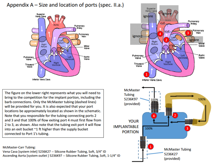
The scope of this class was to prepare the juniors for the senior capstone class. The primary component of this design project was to collaborate as a team to plan, design, prototype, test, and document an engineering product. The design project of this class was to create a purely mechanical artificial heart system that could be used and powered by the patient. The external driver was classified as the method to which the user would power the internal portion or the heart system. This blog post will highlight some of our work in planning, designing, prototyping, testing, and documenting an engineering product. Below is a picture to show the some of the constraints for the internal portion.
From research and input from our professor, that my team and I crafted and polished the design constraints throughout the course of this project.
Design Specs
To see our final design specs please see this pdf: designspecsfinal
Concept Selection
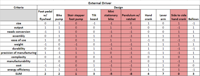
The following collection of screen shots is the team’s concept selection done on all of the designs considered during brainstorming. The goal of this exercise was to limit the number of options to 6-7 maximum for the actual decision matrix. Because of this, the designs were graded only on a -1 to 1 scale, with 1 being the best. No weight was given to any category. The designs highlighted in red were deemed to be poor choices and did not move on to the next round of analysis.
To explain the categories better:
Size: Given the score of 1 if the concept could be small.
Output: Given the score of 1 if the concept could be high.
Output Speed: Given the score of 1 if the concept’s output was not slow.
Needs Conversion: Given the score of 1 if the concept has a low amount of adapters and converters.
Assembly: Given the score of 1 if the concept could be easily put together.
Ease of Use: Given the score of 1 if the concept could be easily used by the user.
Weight: Given the score of 1 if the concept was light weight.
Durability: Given the score of 1 if the concept could last a long time.
Precision of Manufacturing: Given the score of 1 if the concept didn’t require a precise method of manufacturing
Complexity: Given the score of 1 if the concept had a few parts and operations.
Manufacturability: Given the score of 1 if the concept could be created by students, not professionals.
Cost: Given the score of 1 if the concept was low cost.
Ease of Seal: Given the score of 1 if the concept could be sealed easily.
Energy Efficiency: Given the score of 1 if the concept could produce a high output with a low input.
Click on the photos to zoom in
The External Driver Concept Selection:
The Implantable Driver Concept Selection:
Here is a list of the concepts with a picture and a short description:
2-cylinder-engine air-driven-dual-piston bellows bike-pump
circular-compressive-diaphragm circular-expansive-diaphragm continuous-fan-pump-air-center
continuous-fan-pump-air-side continuous-fan-pump-water-center continuous-fan-pump-water-side
cylindrical-expansive-diaphragm foot-pedal-with-flywheel horizontal-hand-crank
lever-arm-with-flywheel mechanical-driven-dual-piston mechanically-compressed-diaphragm
pendulum-air-compressor rotating-disk-valve side-to-side-hand-crank-description_
three-lobes tilt-board trileaflet-valve
Design Matrix
To see more of our we chose our final idea check out this pdf which walks through the design matrix process: decision-matrix
System Testing
To see our final version of our system testing check out this pdf: system-testing
How it worked
Here is what the dual driven piston ended up looking like.
A plastic was placed in between the two halves of the part to create the diagram that would cause the two fluids to move in response to each other. One way values were used to create a single flow of fluid.
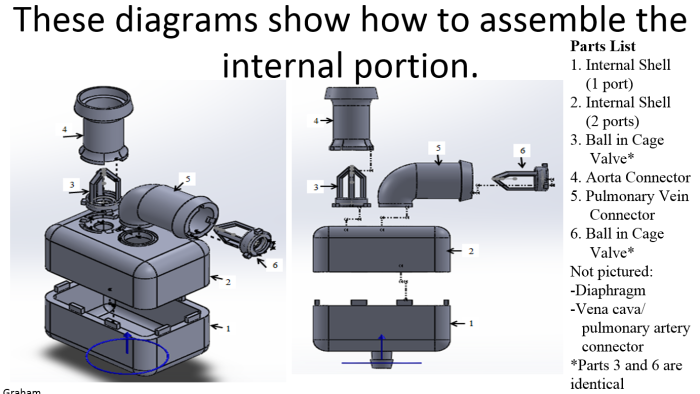
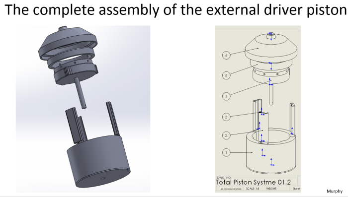
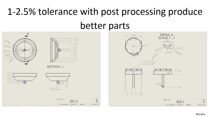
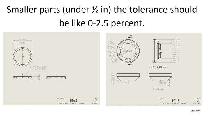
Here is the external driver which I created in SOLIDWORKS 2014. Here is the CAD files.
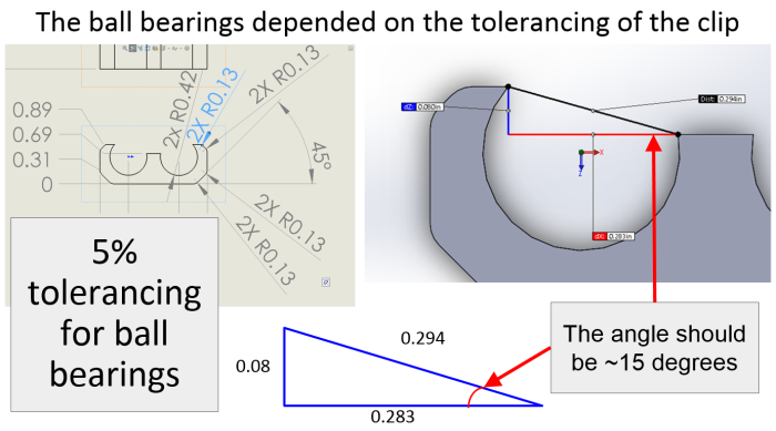
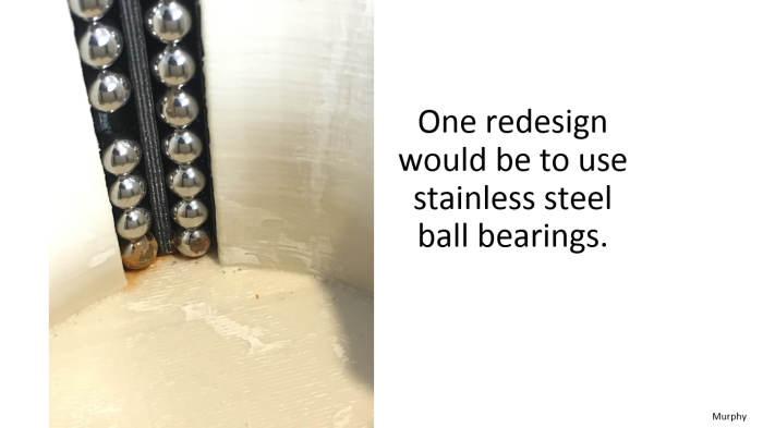
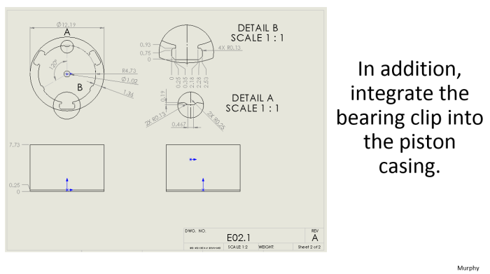
A plastic bag was screwed/glued into parts 4 and 5 and ball bearing were inserted to three clips to create a “friction-less” track for the piston. The external flywheel (not shown) would connect to the shaft and cause the bag containing the driver fluid to expand and contract.
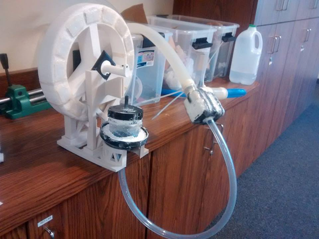
Final Product
While were finishing making our product we were require to present on our project.
Here are the slides that I created
Initial Designs
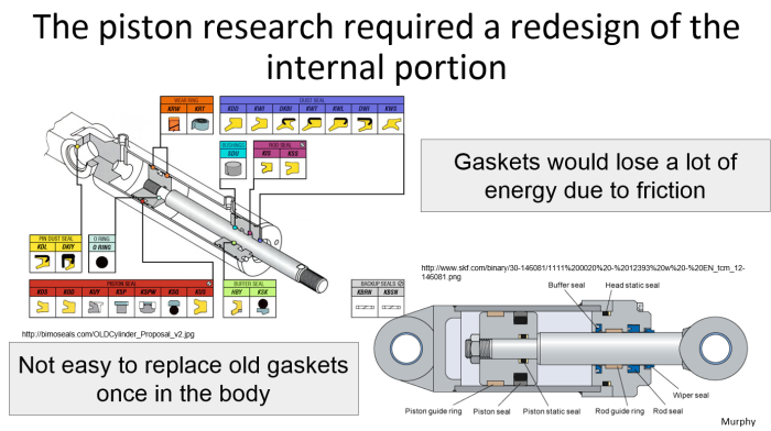
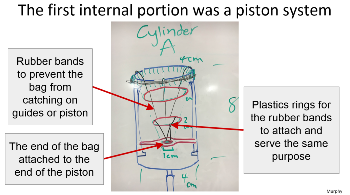
Things we learned about 3D printing and other things
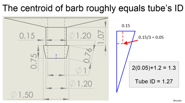
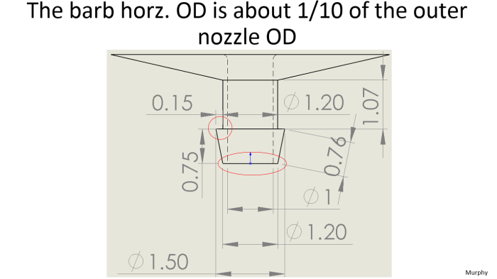
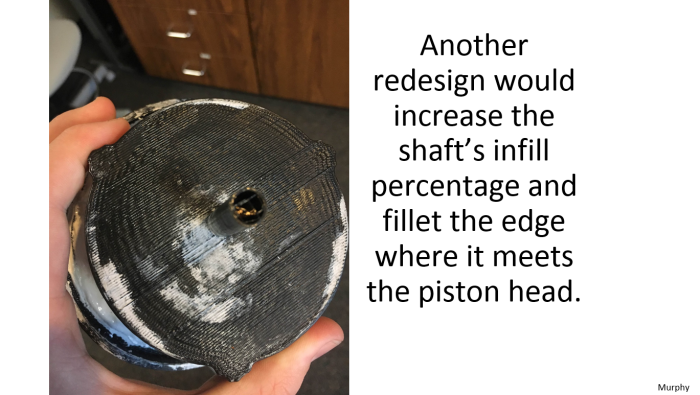
Redesigns to the project we would do if we had more time
Video for the full end of the year presentation
See the video for the full end of the year presentation. Kimberli Graham, Adam Goodwin, Isaac Need, and Max Murphy in the order of presentation.
Here is the pdf of the presentation: kaim-presentation my slides are 35-48
Here is the external driver which I created in SOLIDWORKS 2014. Here is the CAD files.
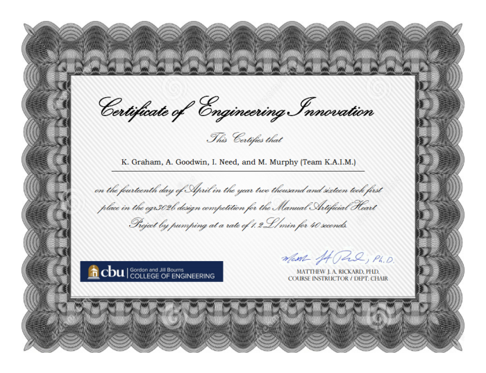
We received the first place award:
